spinner-machine-map
Generate visual maps from the SpiNNaker network topology to board locations.
$ spinner-machine-map -h
usage: spinner-machine-map [-h] [--version] (--num-boards N | --triads W H)
                           [--transformation {shear,slice}]
                           [--uncrinkle-direction {columns,rows}]
                           [--folds X Y] [--board-dimensions W H D]
                           [--board-wire-offset-south-west X Y Z]
                           [--board-wire-offset-north-east X Y Z]
                           [--board-wire-offset-east X Y Z]
                           [--board-wire-offset-west X Y Z]
                           [--board-wire-offset-north X Y Z]
                           [--board-wire-offset-south X Y Z]
                           [--inter-board-spacing S]
                           [--boards-per-frame BOARDS_PER_FRAME]
                           [--frame-dimensions W H D]
                           [--frame-board-offset X Y Z]
                           [--inter-frame-spacing S]
                           [--frames-per-cabinet FRAMES_PER_CABINET]
                           [--cabinet-dimensions W H D]
                           [--cabinet-frame-offset X Y Z]
                           [--inter-cabinet-spacing S] [--num-cabinets N]
                           [--num-frames N]
                           filename [width] [height]

Generate visual maps from the SpiNNaker network topology to board locations.

optional arguments:
  -h, --help            show this help message and exit
  --version, -V         show program's version number and exit

image file parameters:
  filename              filename to write the output to (.pdf or .png)
  width                 width of the image in mm for PDF and pixels for PNG
                        (defaults to 280 mm if PDF and 1000 px for PNG)
  height                height of the image in mm for PDF and pixels for PNG
                        (if only width is given, output will be at most width
                        wide and width tall)

machine topology dimensions:
  --num-boards N, -n N  build the 'squarest' system with this many boards
  --triads W H, -t W H  build a system with the specified number of triads of
                        boards in each dimension (yielding 3*W*H boards)

topology folding options:
  --transformation {shear,slice}, -T {shear,slice}
                        the transformation function to use from hexagonal
                        torus to rectangular Cartesian grid (selected
                        automatically if omitted)
  --uncrinkle-direction {columns,rows}
                        direction in which to uncrinkle the hexagonal mesh to
                        form a regular grid (default: rows)
  --folds X Y, -F X Y   the number of pieces to fold into in each dimension
                        (default: (2, 2)) ignored if --transformation is not
                        given

board physical dimensions:
  --board-dimensions W H D
                        physical board dimensions in meters (default: (0.014,
                        0.233, 0.24))
  --board-wire-offset-south-west X Y Z
                        physical offset of the south-west connector from board
                        left-top-front corner in meters (default: (0.008,
                        0.013, 0.0))
  --board-wire-offset-north-east X Y Z
                        physical offset of the north-east connector from board
                        left-top-front corner in meters (default: (0.008,
                        0.031, 0.0))
  --board-wire-offset-east X Y Z
                        physical offset of the east connector from board left-
                        top-front corner in meters (default: (0.008, 0.049,
                        0.0))
  --board-wire-offset-west X Y Z
                        physical offset of the west connector from board left-
                        top-front corner in meters (default: (0.008, 0.067,
                        0.0))
  --board-wire-offset-north X Y Z
                        physical offset of the north connector from board
                        left-top-front corner in meters (default: (0.008,
                        0.085, 0.0))
  --board-wire-offset-south X Y Z
                        physical offset of the south connector from board
                        left-top-front corner in meters (default: (0.008,
                        0.103, 0.0))
  --inter-board-spacing S
                        physical spacing between each board in a frame in
                        meters (default: 0.00124)

frame physical dimensions:
  --boards-per-frame BOARDS_PER_FRAME
                        number of boards per frame (default: 24)
  --frame-dimensions W H D
                        frame physical dimensions in meters (default: (0.43,
                        0.266, 0.25))
  --frame-board-offset X Y Z
                        physical offset of the left-top-front corner of the
                        left-most board from the left-top-front corner of a
                        frame in meters (default: (0.06, 0.017, 0.0))
  --inter-frame-spacing S
                        physical spacing between frames in a cabinet in meters
                        (default: 0.089)

cabinet physical dimensions:
  --frames-per-cabinet FRAMES_PER_CABINET
                        number of frames per cabinet (default: 5)
  --cabinet-dimensions W H D
                        cabinet physical dimensions in meters (default: (0.6,
                        1.822, 0.25))
  --cabinet-frame-offset X Y Z
                        physical offset of the left-top-front corner of the
                        top frame from the left-top-front corner of a cabinet
                        in meters (default: (0.085, 0.047, 0.0))
  --inter-cabinet-spacing S
                        physical spacing between each cabinet in meters
                        (default: 0.0)
  --num-cabinets N, -c N
                        specify how many cabinets to spread the system over
                        (default: the minimum possible)
  --num-frames N, -f N  when only one cabinet is required, specifies how many
                        frames within that cabinet the system should be spread
                        across (default: the minimum possible)
Chip-to-Board Location Maps
To aid in diagnosing hardware-related issues in large SpiNNaker applications, SpiNNer can generate maps which show where each board boundary and board-to-board link in the system lies:
$ spiner-machine-map -n 24 out.png
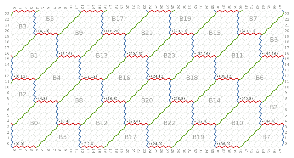
PDF and PNG output are supported.
In the diagram, each hexagon represents a SpiNNaker chip and board boundaries are clearly marked. The coordinates of each Ethernet connected chip is indicated in the bottom-left corner of each board. The physical location of each board is labelled in large grey text. Depending on the size of the system, the cabinet, frame and board numbers are given (prefixed with ‘C’, ‘F’ and ‘B’ respectively).
Board boundaries are coloured to indicate which board-to-board link is responsible for each chip-to-chip link:
| Direction | Colour |
|---|---|
| North/South | Red |
| East/West | Green |
| North-East/South-West | Blue |
For a complementary visual mapping from physical board positions to SpiNNaker chip coordinates, see the spinner-wiring-diagram command. Alternatively, for a machine-readable mapping, see the spinner-ethernet-chips command.